
If you’ve got an LED module on the bench and no configuration file for it, the NovaStar Smart Settings wizard in NovaLCT is how you build one. The output is an RCFGX file: the receiving-card configuration that tells the card exactly how your module is wired, scanned and driven. Without it, the module lights up as noise or not at all. This guide walks through the NovaStar Smart Settings RCFGX workflow from start to finish — the same process we use when retrofitting undocumented screens and commissioning NovaStar control on our DX and DFC fixed-install ranges.
The process takes about twenty minutes once the hardware is connected. You answer a series of prompts while watching what the module actually displays, trace a flashing pixel to map the scan path, then save the result as a named configuration you can load onto every receiving card in the LED screen.
Key takeaways
- An RCFGX file is a NovaStar receiving-card configuration file. It defines how a specific LED module is scanned and driven, and one file can be loaded onto every compatible receiving card in a screen.
- Before you start, you need three facts from the module supplier or datasheet: the driver IC model, the decoding IC model, and the module resolution in pixels (width × height).
- If your exact driver chip isn’t in the NovaLCT list, select the common (general) chip option and continue. That is NovaStar’s own guidance, not a workaround.
- Data groups = module pixel height ÷ number of simultaneously lighted rows. Note this figure down; it’s used later in cabinet configuration.
- The wizard finishes with pixel tracing. When NovaLCT reports the running line table is complete, save the configuration with a clear name and it can be exported and shared as an .rcfgx file.
At a glance: the Smart Settings workflow
| Item | Detail |
|---|---|
| Software | NovaLCT (advanced synchronous-mode login, password admin) |
| Output | RCFGX file (receiving-card configuration) |
| Required module data | Driver IC model, decoding IC model, pixel resolution (W × H) |
| Example module in this guide | 64 × 32 px, SM16026 driver IC, 74HC138 decoding IC |
| Data type | Parallel drive |
| Control connection | USB from PC to sending card |
| Video connection | DVI from PC to sending card |
| Test module position | Hub-card connector J-H1, receiving card 1, port 1 |
| Windows setup | 100% scaling, resolution ≥ LED screen, duplicate display mode |
| Typical duration | 15–25 minutes with hardware already connected |
What an RCFGX file is and where it sits in the signal chain
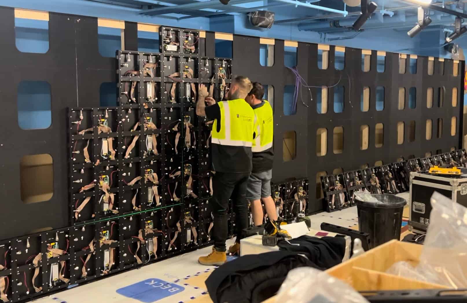
An RCFGX file is the receiving card’s instruction set: scan type, data groups, driver and decoding IC behaviour, and the running line table that records the physical order in which pixels are addressed. Load the right file and the module displays correctly. Load the wrong one and you get ghosting, scrambled blocks, or a dead panel.
That instruction set matters because the receiving card is generic hardware. Every NovaStar-driven LED screen has the same basic chain — a source feeds a sending card, the sending card feeds receiving cards over Ethernet, and each receiving card drives its modules through a hub card. In practice that usually means an MCTRL- or VX-series sending card feeding Armor-series receiving cards. We’ve broken this down piece by piece in our LED video wall signal chain explained guide, and the receiving card has no idea whether it’s driving a fine-pitch indoor module or a coarse outdoor one until the RCFGX file tells it.
One caution before borrowing a file from elsewhere: two modules can be the same size and still be wired completely differently — same resolution doesn’t mean same file. Different chips, scan arrangements or pixel orders behind identical dimensions need different configurations.
For most new screens you never build this file yourself, because the cabinet manufacturer supplies it. Where Smart Settings earns its keep is when no file exists: legacy screens with lost documentation, mixed-batch modules, or a control-system upgrade where the old processor is being swapped out. That last case comes up constantly in our guide to retrofitting receiving cards and controllers on legacy screens, where a perfectly good set of cabinets just needs new electronics — replacing the controller does not automatically recreate the module-specific RCFGX file.
What you need before opening NovaLCT
The wizard asks questions you cannot answer by guesswork, so gather this first:
- Driver IC model. The chip that drives the LEDs, from the module supplier or datasheet. The example module in this guide uses an SM16026.
- Decoding IC model. The row-decoding chip, again from the datasheet. The example module uses a 74HC138, one of the most common decoders in the industry.
- Module pixel resolution. Width × height in pixels for one module — not the cabinet, not the full screen. The example module is 64 × 32. Don’t infer it from cabinet dimensions or pixel pitch: pitch describes the spacing between pixels, resolution describes how many the module contains. Our DVLED pixel pitch guide covers that relationship in detail. If the paperwork is missing, count the LEDs on the physical module; on fine-pitch product a zoomed-in photo of one corner makes this much easier.
Then connect the hardware. USB from the PC to the sending card carries the control signal; DVI carries the video. The two paths have distinct jobs — USB alone doesn’t provide the test image, and DVI alone doesn’t give NovaLCT control of the sending card. Ethernet runs from the sending card to the receiving card, and flat cables from the receiving card to the module, all seated properly.
One detail people miss: the test module must be connected to the first slot (J-H1) of the hub card on the first receiving card, which itself hangs off the first port of the sending card. The wizard’s test patterns target that position. The sending card should be connected directly to the PC with no third-party device in between, and any scaling function turned off.
You only need one module connected. Configure one module correctly and the resulting RCFGX file applies to every identical module in the screen.
Step-by-step: creating the RCFGX file with Smart Settings
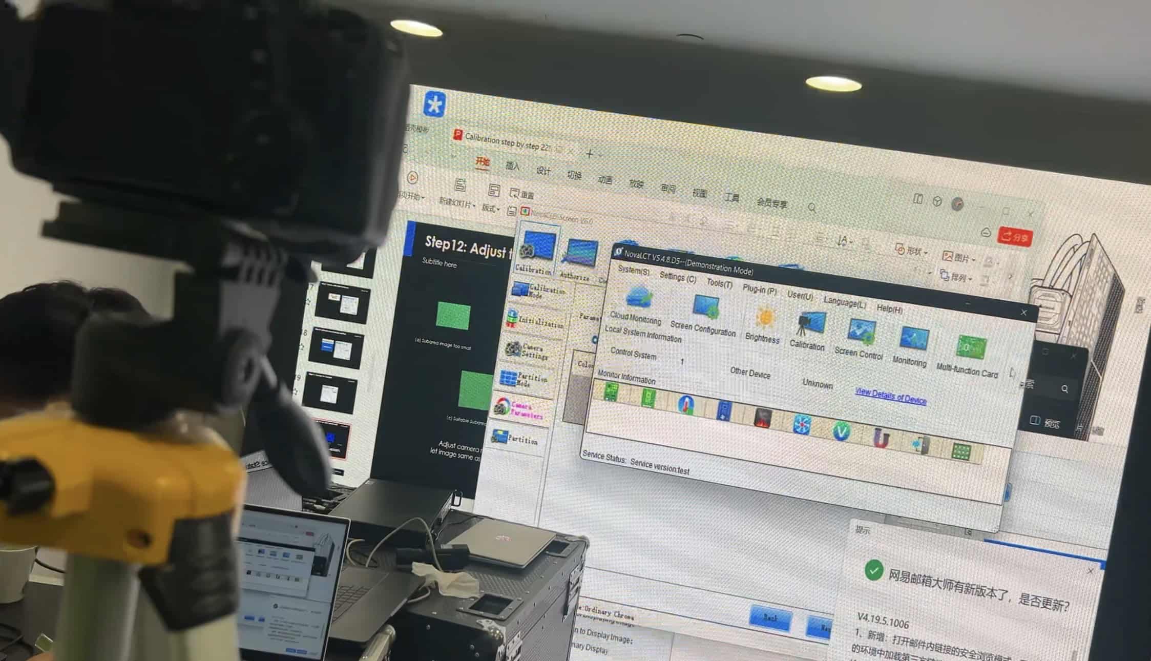
Creating an RCFGX file in NovaLCT takes eight steps: set Windows to 100% scaling and duplicate display mode, log in with the advanced synchronous user, set the sending card resolution, enter the driver IC, decoding IC and module resolution, confirm the colours the module actually displays, count the lighted rows, trace the pixel path, and save. The sequence below follows the official NovaStar Smart Settings tutorial video and reflects current NovaLCT releases; when obtaining NovaLCT itself, download it from NovaStar’s official site rather than an unidentified software mirror.
Step 1: Prepare the Windows graphics output
On Windows 10, right-click the desktop and select Display settings. Then:
- Under Scale and layout, set scaling to 100%.
- Set the output resolution equal to or higher than the resolution of the LED screen.
- Under Multiple displays, select Duplicate these displays, then click Keep changes.
Windows scaling is the silent killer here. At 125% or 150%, the pixel mapping between the graphics card and the screen no longer lines up one-to-one, and the observation steps later in the wizard become unreliable.
Step 2: Log in to NovaLCT and set the sending card
Open NovaLCT, click User, and choose the advanced synchronous system user login. The password is admin. Click Screen Configuration, then Next.
On the Sending Card tab, go to the source configuration area and change the resolution to match the output resolution of the graphics card. Click Set, then Refresh to confirm the setting took. This is the graphics canvas presented to the sending card — separate from the module resolution you enter next.
Step 3: Launch the Smart Settings wizard
Move to the Receiving Card tab, select Smart Settings, and click Next. Everything from here on is the wizard.
Step 4: Enter the chip and module details
The first wizard page asks for the facts you gathered earlier:
- Driver chip. Click the chip-type selector and find your driver IC. If the exact model isn’t listed — as with the SM16026 — select the common chip option and click OK. Don’t pick a different named chip because its number looks similar.
- Data type. Select parallel drive.
- Module resolution. Enter width and height in pixels: 64 × 32 for the example module.
- Decoding IC. Select your decoder, 74HC138 in this case.
Click Next.
Step 5: Confirm what the module displays
From this point the wizard shows test states on the physical module, and your job is to report what you see. Keep an eye on the module itself, not just the laptop.
First the module displays a black screen; confirm full black and click Next. If it isn’t fully black, stop and check the connections and module details rather than pressing on. Then the wizard cycles colour prompts. Switch to manual and select the colour the module is actually showing for each prompt (red, green, blue, black) so NovaLCT can map the colour channels correctly. If the interface requests one state but the module visibly produces another colour, report the visible one — choosing the expected colour instead carries a channel error into the finished file.
Step 6: Count lighted rows and calculate data groups
The wizard now lights a set of rows or columns on the module simultaneously. Count them on the module itself and enter the number. It repeats this in the following step; count and enter again.
This stage also tells you how many data groups the module uses. A data group is a pixel area that’s scanned independently, and the maths is simple: data groups = module pixel height ÷ number of lighted rows. A 32-pixel-high module showing 2 lighted rows uses 16 data groups. If it doesn’t divide cleanly, you’ve miscounted. Count again, close up. Write the figure down; it’s used later when building the cabinet configuration.
Step 7: Trace the pixels
Now the wizard flashes a single pixel on the module and asks you to draw its path on screen. Click the corresponding positions in NovaLCT one by one, following the lighted pixel, or use the keyboard arrow keys. Once you’ve established the pattern for a row, click automatic generation and NovaLCT completes it while you verify the flashing pixels still match. If the trace goes the wrong way, fix it before moving on — the wizard will happily save a wrong one.
When the trace is done, NovaLCT pops up a message confirming the running line table is complete. Click OK, then Next. This table is the heart of the configuration: it records the physical scan order of every pixel on the module.
Step 8: Save the configuration
Enter a name for the module configuration and click Complete. Be descriptive: pitch, module size, driver IC and date will save someone a headache in three years, and a generic name like screen.rcfgx is a liability on any site with more than one module type. This saved configuration is what gets exported and shared as the RCFGX file, ready to load onto every receiving card in the screen or send to another engineer.
Finally, move the cursor to the upper-left corner of the desktop and check the module is displaying correctly. If the picture is clean, the configuration works.
After the wizard: loading, sharing and knowing the file’s limits
One RCFGX file can be loaded onto every receiving card in an LED screen, provided all the modules genuinely share the same driver IC, decoding IC, resolution and internal addressing. Screens part-repaired over the years with mixed module batches may need separate files, and that’s worth checking before writing one configuration across an entire wall. Keep a copy of the RCFGX file with the site documentation, and save it somewhere that survives a laptop change; a configuration file living only on one engineer’s old machine is how screens end up orphaned.
It also helps fault-finding to know what the file does not configure: the Windows graphics output, the sending-card canvas, cabinet placement across output ports, content scheduling and remote monitoring are all separate layers. A corrupted image at module level points towards receiving-card configuration, hub connections or module behaviour; correct test patterns with misplaced content suggest the problem sits in the mapping or video path instead. If you’re recovering an undocumented screen as part of bringing several sites under central control, the publishing and monitoring layer is the next thing to sort — that’s where NovaStar’s cloud CMS platform comes in for multi-site operators.
If the module never displays the wizard’s test states at all, check the basics in order: USB and DVI both connected (they do different jobs), module on J-H1 of receiving card 1, port 1, Windows in duplicate mode, and the NovaLCT sending-card resolution matching the graphics output.
If you’re building a screen spec from the ground up rather than rescuing an existing one, our NovaStar LED processor calculator helps size the sending side, and our LED screen configurator produces a spec with the control system already matched to the panel. And if you’d rather hand the whole commissioning job to us, get in touch — we configure and commission NovaStar systems on our DX and DFC fixed-install ranges as standard.
From the field: Smart Settings on an undocumented screen
The job that made me properly learn Smart Settings was a retrofit on a screen where the original installer had disappeared and taken every scrap of documentation with them. No config file, no datasheet, nothing but the cabinets on the wall. I pulled a module, found the driver and decoder ICs under a magnifier, counted the pixels, and ran the wizard exactly as NovaStar teaches it. Forty minutes later the screen was alive again on new receiving cards.
What stuck with me is how much of the wizard is just careful observation. My advice: don’t rush the colour-matching and row-counting steps, because a wrong count there means a garbage running line table at the end and you start again. During the pixel trace I slow down and follow the light rather than anticipating the route — the table looks repetitive and it’s easy to assume the next direction. The module is the reference. Get the boring steps right and the trace at the end is almost satisfying.
NovaStar Smart Settings RCFGX: Frequently Asked Questions
How do I create an RCFGX file in NovaLCT?
Gather the module’s driver IC model, decoding IC model and pixel resolution, then run the Smart Settings wizard from the Receiving Card tab in NovaLCT. The wizard walks through colour confirmation, row counting and pixel tracing on a connected test module, then saves the result as a named configuration you can export as an .rcfgx file. With hardware connected, it takes 15–25 minutes.
What is an RCFGX file?
An RCFGX file is a NovaStar receiving-card configuration file. It stores everything a receiving card needs to drive a specific LED module correctly: driver and decoding IC behaviour, data groups, scan mapping and the running line table. Once created through Smart Settings in NovaLCT, the same file can be loaded onto every receiving card in a screen or shared with other engineers.
What information do I need before running Smart Settings?
Three things: the driver IC model, the decoding IC model, and the module’s pixel resolution as width × height. All three normally come from the module supplier or datasheet — the example in this guide is 64 × 32 pixels with an SM16026 driver IC and a 74HC138 decoding IC. If paperwork is missing, the ICs can be read off the chips themselves.
What if my driver chip isn’t listed in NovaLCT?
Select the common chip (general) option and continue. This is NovaStar’s own guidance in the official training material, where the demo module’s SM16026 driver isn’t in the chip list either. The observation and pixel-tracing steps that follow establish the module’s actual behaviour, so the wizard still produces a working configuration for most standard modules.
Why does the module need to be on connector J-H1 of receiving card 1?
The Smart Settings wizard sends its test patterns to a known position: the first hub-card slot (J-H1) on the first receiving card, connected to the first port of the sending card. If the test module sits anywhere else, the patterns don’t reach it and the observation steps fail. Only one module needs to be connected for the whole process.
How do I work out the number of data groups?
Divide the module’s pixel height by the number of simultaneously lighted rows shown during the counting step of the wizard. A 32-pixel-high module displaying 2 lighted rows at once uses 16 data groups. The row count must come from the observed pattern on the connected module, and the figure is worth recording because it’s used later in cabinet configuration.
Can I use one RCFGX file for a whole screen?
Yes, provided every module is genuinely identical. The file describes the module type, not an individual panel, so one configured module covers the screen. But same size doesn’t mean same file — different driver ICs, decoding arrangements or pixel routes need separate configurations, a common discovery on older screens that have been part-repaired with mixed batches.
Do I need Smart Settings for a brand-new LED screen?
Usually not. On our own DX and DFC fixed-install projects the receiving-card configuration arrives already tested with the cabinets. Smart Settings matters when no file exists: legacy screens with lost documentation, controller retrofits, or unbranded modules bought without support. It’s how you get a working configuration for a module nobody has paperwork for.
Conclusion
Get the three module facts, prepare Windows properly, do the wizard slowly, and save the file with a proper name — that’s the whole job. Don’t push an unproven file to a whole wall until one module proves it, and keep the saved RCFGX with the project records so the next engineer isn’t back at square one. Using NovaStar Smart Settings to create an RCFGX file is what turns an undocumented module into a documented, driveable screen the same day. If you’d rather we handled the configuration, commissioning or a full controller upgrade, contact us or call +44 (0)203 489 9878 and we’ll take it from there.